Mazda 2: On-Board Diagnostic Test
DTC Reading Procedure
1. Connect the M-MDS (IDS) to the DLC-2.
2. After the vehicle is identified, select the following items from the initialization screen of the IDS.
- Select "Self Test".
- Select "Modules".
- Select "PCM".
3. Then, select the "Retrieve CMDTCs" and perform procedures according to directions on the IDS screen.
4. Verify the DTC according to the directions on the IDS screen.
- If any DTCs are displayed, perform troubleshooting according to the corresponding DTC inspection.
5. After completion of repairs, clear all DTCs stored in the PCM, while referring to "AFTER REPAIR PROCEDURE".
Pending Trouble Code Access Procedure
1. Connect the M-MDS (IDS) to the DLC-2.
2. After the vehicle is identified, select the following items from the initialization screen of the IDS.
- Select "Self Test".
- Select "Modules".
- Select "PCM".
3. Then, select the "Retrieve CMDTCs" and perform procedures according to directions on the IDS screen.
4. Retrieve the pending trouble codes according to the directions on the IDS screen.
Freeze Frame PID Data Access Procedure
1. Connect the M-MDS (IDS) to the DLC-2.
2. After the vehicle is identified, select the following items from the initialization screen of the IDS.
- Select "Self Test".
- Select "Modules".
- Select "PCM".
3. Then, select the "Retrieve CMDTCs" and perform procedures according to directions on the IDS screen.
4. Retrieve the freeze frame PID data according to the directions on the IDS screen.
NOTE:
- Freeze frame data/snapshot data appears at the top of the help screen when the displayed DTC is selected.
Freeze frame data
- The freeze frame data consists of data for vehicle and engine control system operation conditions when malfunctions in the engine control system are detected and stored in the PCM.
- Freeze frame data is stored at the instant the malfunction indicator lamp illuminates, and only a part of the DTC data is stored.
- For the freeze frame data, if there are several malfunctions in the engine control system, the data for the malfunction which occurred initially is stored. Thereafter, if a misfire or fuel injection control malfunction occurs, data from the misfire or fuel injection control malfunction is written over the initially stored data. However, if the initially stored freeze frame data is a misfire or fuel injection control malfunction, it is not overwritten.
Snapshot data
- The snapshot data stores the currently detected DTC data.
- The recording timing for the freeze frame data/snapshot data differs
depending on the number of DTC drive cycles.
- For a DTC with a drive cycle number 1, only the malfunction determination data is recorded.
- For a DTC with a drive cycle number 2, both the malfunction determination and undetermined data is recorded.
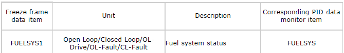
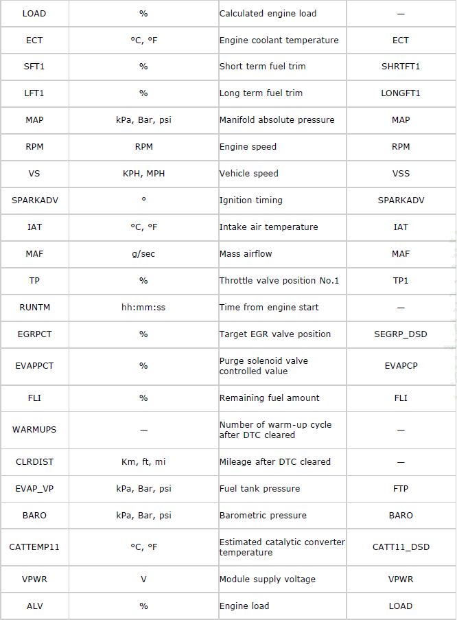
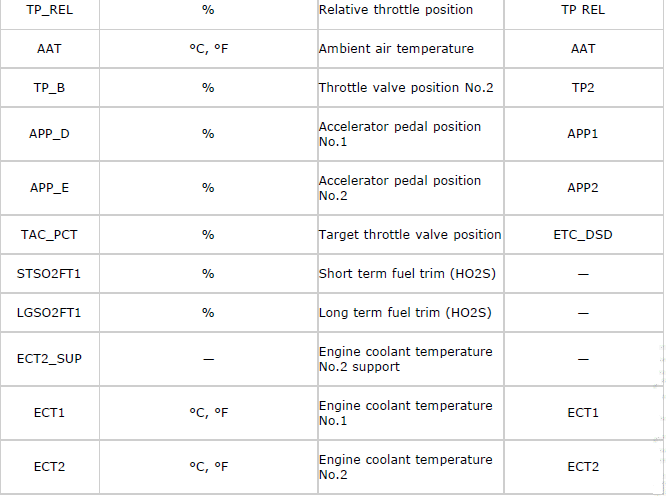
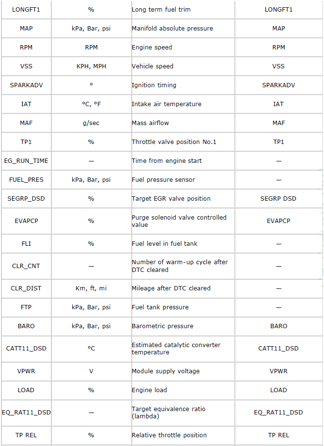
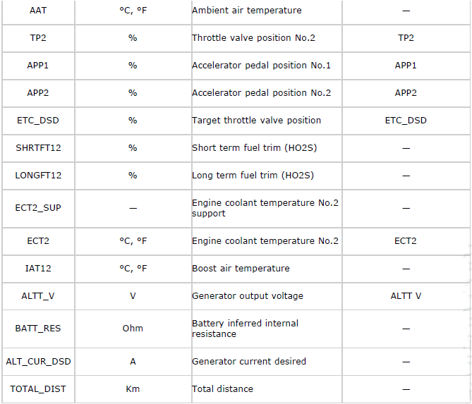
Freeze frame data table
NOTE:
- Refer to PID monitor table for confirm the engine control system operation status while the PCM does not store the DTC. (See PCM INSPECTION).
- Freeze frame data items are not displayed, according to detected DTC.
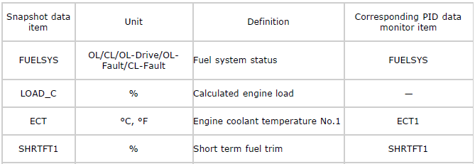
Snapshot data table
NOTE:
- Refer to PID monitor table for confirm the engine control system operation status while the PCM does not store the DTC. (See PCM INSPECTION).
- Snapshot data items are not displayed, according to detected DTC.
On-Board System Readiness Tests Access Procedure
1. Connect the M-MDS (IDS) to the DLC-2.
2. After the vehicle is identified, select the following items from the initialization screen of the IDS.
- Select "Powertrain".
- Select "OBD Test Modes".
- Select "Mode 1 Powertrain Data".
- Select "PCM".
3. Then, select the "***SUP" and "**EVAL" PIDs in the PID selection screen.
4. Monitor those PIDs and check it system monitor is completed.
NOTE:
- If the on-board system readiness tests are not completed the PCM stores DTC P1000.
PID/DATA Monitor and Record Procedure
NOTE:
- The PID data screen function is used for monitoring the calculated value of input/output signals in the module. Therefore, if the monitored value of the output parts is not within the specification, it is necessary to inspect the monitored value of input parts corresponding to the applicable output part control. In addition, because the system does not display an output part malfunction as an abnormality in the monitored value, it is necessary to inspect the output parts individually.
1. Connect the M-MDS (IDS) to the DLC-2.
2. After the vehicle is identified, select the following items from the initialization screen of the IDS.
- Select "DataLogger".
- Select "Modules".
- Select "PCM".
3. Select the applicable PID from the PID table.
4. Verify the PID data according to the detections on the screen.
Diagnostic Monitoring Test Results Access Procedure
1. Connect the M-MDS (IDS) to the DLC-2.
2. After the vehicle is identified, select the following items from the initialization screen of the IDS.
- Select "Powertrain".
- Select "OBD Test Modes".
- Select "Mode 6 On-Board Test Results".
3. Verify the diagnostic monitoring test result according to the directions on the IDS screen.
Active Command Modes Procedure
1. Connect the M-MDS (IDS) to the DLC-2.
2. After the vehicle is identified, select the following items from the initialization screen of the IDS.
- Select "DataLogger".
- Select "Modules".
- Select "PCM".
3. Select the simulation items from the PID table.
4. Using the active command modes function, inspect the operations for each parts.
- If the operation of output parts cannot be verified after the active command mode inspection is performed, this could indicate the possibility of an open or short circuit, sticking, or operation malfunction in the output parts.
AFTER REPAIR PROCEDURE
1. Connect the M-MDS (IDS) to the DLC-2.
2. After the vehicle is identified, select the following items from the initialization screen of the IDS.
- Select "Self Test".
- Select "Modules".
- Select "PCM".
- Select "Retrieve CMDTCs".
3. Verify the DTC according to the directions on the IDS screen.
4. Press the clear button on the DTC screen to clear the DTC.
5. Verify that no DTCs are displayed.
KOEO/KOER SELF TEST
KOEO Self Test
1. Connect the M-MDS (IDS) to the DLC-2.
2. After the vehicle is identified, select the following items from the initialization screen of the IDS.
- Select "Self Test".
- Select "Modules".
- Select "PCM".
3. Then, select the "KOEO On Demand Self Test" and perform procedures according to directions on the IDS screen.
4. Verify the DTC according to the directions on the IDS screen.
- If any DTCs are displayed, perform troubleshooting according to the corresponding DTC inspection.
5. After completion of repairs, clear all DTCs stored in the PCM, while referring to "AFTER REPAIR PROCEDURE".
KOER Self Test
NOTE:
- Perform a KOER self test while idling.
1. Connect the M-MDS (IDS) to the DLC-2.
2. Start the engine and run it at idle.
3. After the vehicle is identified, select the following items from the initialization screen of the IDS.
- Select "Self Test".
- Select "Modules".
- Select "PCM".
4. Then, select the "KOER On Demand Self Test" and perform procedures according to directions on the IDS screen.
5. Verify the DTC according to the directions on the IDS screen.
- If any DTCs are displayed, perform troubleshooting according to the corresponding DTC inspection.
6. After completion of repairs, clear all DTCs stored in the PCM, while referring to "AFTER REPAIR PROCEDURE".

