Mazda 2: Dashboard
DASHBOARD REMOVAL/INSTALLATION
1. Disconnect the negative battery cable.
2. Remove the following parts:
- Glove compartment (See GLOVE COMPARTMENT REMOVAL/INSTALLATION).
- Dashboard under cover (See DASHBOARD UNDER COVER REMOVAL/INSTALLATION).
- Heat duct (passenger side) (See HEAT DUCT COMPONENT REMOVAL/INSTALLATION).
- Rear console (See REAR CONSOLE REMOVAL/INSTALLATION).
- Shift lever knob (MTX) (See MANUAL TRANSAXLE SHIFT MECHANISM REMOVAL/INSTALLATION).
- Side wall (See SIDE WALL REMOVAL/INSTALLATION).
- Front console component (See FRONT CONSOLE COMPONENT REMOVAL/INSTALLATION).
- Front scuff plate (See FRONT SCUFF PLATE REMOVAL/INSTALLATION).
- Front side trim (See FRONT SIDE TRIM REMOVAL/INSTALLATION).
- Hood release lever (See HOOD LATCH AND RELEASE LEVER REMOVAL/INSTALLATION).
- Driver-side lower panel (See LOWER PANEL REMOVAL/INSTALLATION).
- Knee bolster (See KNEE BOLSTER REMOVAL/INSTALLATION).
- Driver-side air bag module (See DRIVER-SIDE AIR BAG MODULE REMOVAL/INSTALLATION).
- Steering wheel (See STEERING WHEEL AND COLUMN REMOVAL/INSTALLATION).
- Column cover (See COLUMN COVER REMOVAL/INSTALLATION).
- Meter hood (See METER HOOD REMOVAL/INSTALLATION).
- Instrument cluster (See INSTRUMENT CLUSTER REMOVAL/INSTALLATION).
- Combination switch (See COMBINATION SWITCH REMOVAL/INSTALLATION).
- Center panel unit (vehicles with audio unit) (See CENTER PANEL UNIT REMOVAL/INSTALLATION).
- Climate control unit (See CLIMATE CONTROL UNIT REMOVAL/INSTALLATION [MANUAL AIR CONDITIONER] ).
- Shift lever (MTX) (See MANUAL TRANSAXLE SHIFT MECHANISM REMOVAL/INSTALLATION).
- Selector lever (ATX) (See AUTOMATIC TRANSAXLE SHIFT MECHANISM REMOVAL/INSTALLATION).
- Interlock cable (See AUTOMATIC TRANSAXLE SHIFT MECHANISM REMOVAL/INSTALLATION).
- Passenger-side lower panel (See LOWER PANEL REMOVAL/INSTALLATION).
- Side panel (See SIDE PANEL REMOVAL/INSTALLATION).
- A-pillar trim (See A-PILLAR TRIM REMOVAL/INSTALLATION).
- Windshield wiper arm and blade (See WINDSHIELD WIPER ARM AND BLADE REMOVAL/INSTALLATION).
- Cowl grille (See COWL GRILLE REMOVAL/INSTALLATION).
- Sail garnish (See SAIL GARNISH REMOVAL/INSTALLATION).
- Windshield wiper motor (See WINDSHIELD WIPER MOTOR REMOVAL/INSTALLATION).
- Steering shaft cover (See STEERING WHEEL AND COLUMN REMOVAL/INSTALLATION).
- Steering shaft (See STEERING WHEEL AND COLUMN REMOVAL/INSTALLATION).
3. Disconnect antenna feeder No.2 from the antenna feeder No.1. (See ANTENNA FEEDER NO.2 REMOVAL/INSTALLATION)
4. Disconnect antenna feeder No.1 clip from the A-pillar inner panel.
5. Disconnect the dashboard wiring harness connectors.
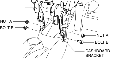
6. Remove nuts A and bolts B then remove the dashboard bracket.
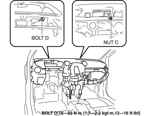
7. Remove nut C and bolt D from the outside of the vehicle (upper dashboard area).
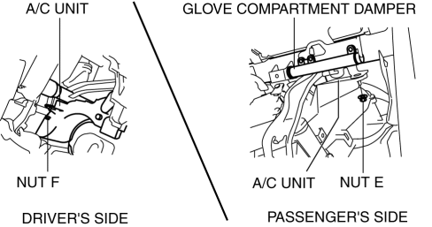
8. Remove nuts E and F shown in the figure.
9. Disconnect the A/C unit related connector.
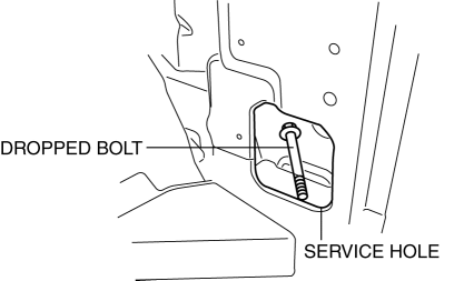
10. Remove the caps, remove bolts I and J. (See Bolt I Removal/Installation Note)
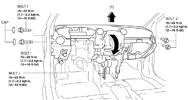
11. Lift the dashboard in the direction of the arrow (1) shown in the figure, disconnect the A/C unit, and then rotate the dashboard in the direction of the arrow (2) and remove it from the vehicle. (See Dashboard Removal Note) 12. Install in the reverse order of removal.
Dashboard Removal Note
WARNING:
- When the dashboard is removed from the vehicle, it could fall and cause injury. Always perform the procedure with at least another person to prevent the dashboard from falling.
CAUTION:
- When the dashboard is removed from the vehicle, be careful not to damage the door and surrounding area.
1. Take the dashboard out through the opened front door.
Bolt I Removal/Installation Note
1. If the bolt falls off during the removal and installation procedure, remove it from the service hole shown in the figure.
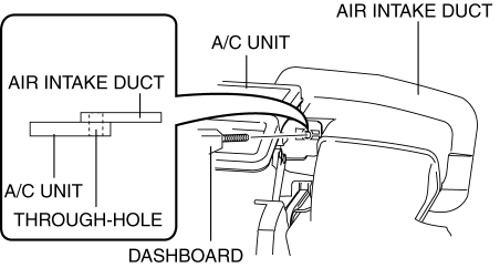
Dashboard Installation Note
1. When inserting the bolt on the dashboard side, verify that the through-hole positions of the air intake duct and A/C unit are aligned.
DASHBOARD DISASSEMBLY/ASSEMBLY
1. Disassemble in the order indicated in the table.
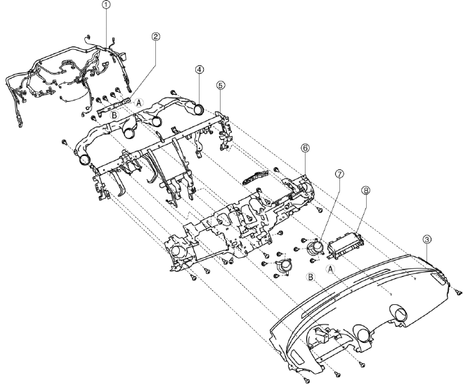
- Dashboard wiring harness
- Dashboard bracket
- Upper garnish
- Duct
- Dashboard member
- Dashboard
- Center ventilator grille
- Passenger-side airbag module
2. Assemble in the reverse order of disassembly.
METER HOOD REMOVAL/INSTALLATION
1. Pull the meter hood in the direction of the arrow shown in the figure and remove it while detaching the clips.
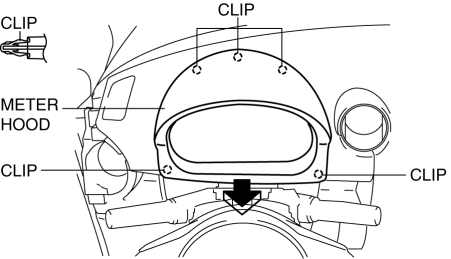
2. Install in the reverse order of removal.
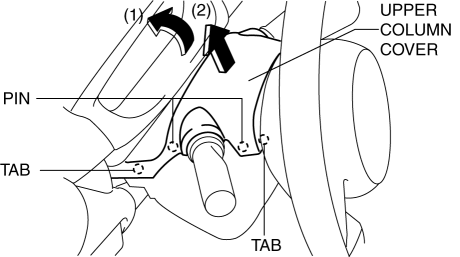
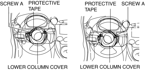
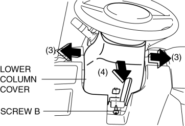
COLUMN COVER REMOVAL/INSTALLATION
1. Pull down the steering wheel.
2. Pull the upper column cover in the direction of the arrow in the order of (1) and (2), then remove the upper column cover while detaching the tabs and pins.
3. Rotate the steering wheel to the left and right until it reaches the positions shown in the figure and remove screws A.
4. Pull up the steering wheel.
5. Remove screw B, then remove the lower column cover in the direction of the arrow (4) while keeping it open in the direction of the arrow (3) shown in the figure.
6. Install in the reverse order of removal.
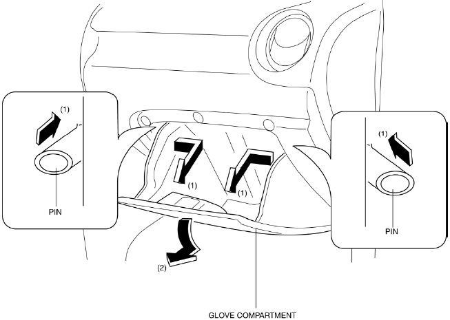
GLOVE COMPARTMENT REMOVAL/INSTALLATION
1. Push both ends of the inner-side glove compartment in the direction of the arrow (1) shown in the figure, detach the pins from the dashboard, and remove the glove compartment in the direction of the arrow (2).
2. Install in the reverse order of removal.
LOWER PANEL REMOVAL/INSTALLATION
Driver's Side
1. Disconnect the negative battery cable.
2. Remove the following parts:
- Front scuff plate (See FRONT SCUFF PLATE REMOVAL/INSTALLATION)
- Front side trim (See FRONT SIDE TRIM REMOVAL/INSTALLATION)
- Rear console (See REAR CONSOLE REMOVAL/INSTALLATION).
- Shift lever knob (MTX) (See MANUAL TRANSAXLE SHIFT MECHANISM REMOVAL/INSTALLATION [F35M-R])
- Side wall (See SIDE WALL REMOVAL/INSTALLATION)
- Front console component (See FRONT CONSOLE COMPONENT REMOVAL/INSTALLATION).
- Hood release lever (See HOOD LATCH AND RELEASE LEVER REMOVAL/INSTALLATION)
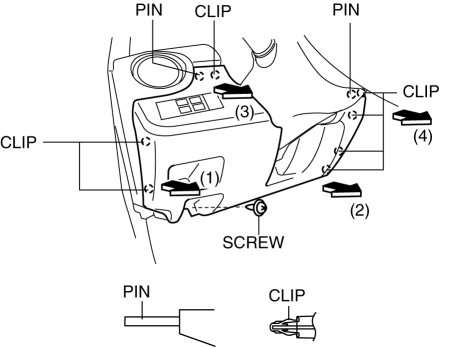
3. Remove the screw, pull the lower panel in the direction of the arrow in the order of (1) , (2), (3), (4) and remove the lower panel while detaching the clips and pins.
4. Disconnect the switch connector.
5. Install in the reverse order of removal.
Passenger's Side
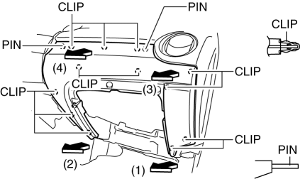
1. Remove the front scuff plate. (See FRONT SCUFF PLATE REMOVAL/INSTALLATION) 2. Remove the front side trim. (See FRONT SIDE TRIM REMOVAL/INSTALLATION) 3. Pull the lower panel in the direction of the arrow in the order of (1), (2), (3), (4) then remove it while detaching the clips and pins.
4. Install in the reverse order of removal.

