Mazda 2: Center Ventilator Grille
CENTER VENTILATOR GRILLE REMOVAL/INSTALLATION
Removal
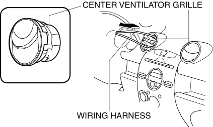
1. Route the wiring harness as shown in the figure and pull on the center ventilator grille in the direction of the arrow to remove it.
Installation
NOTE:
- The center ventilator grille service part is shipped with a center ventilator grille cover as a single unit. Before installing the center ventilator grille, remove the center ventilator grille cover.
1. Insert a flathead screwdriver into the position shown in the figure.
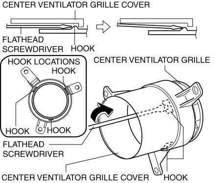
2. Move a flathead screwdriver in the direction of the arrow and detach the hook, while pull the center ventilator grille.
3. Remove the center ventilator grille in the direction of the arrow from the center ventilator grille cover.
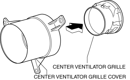
4. Push the center ventilator grille in the direction of the arrow and install it.
VENTILATOR GRILLE REMOVAL/INSTALLATION
1. Remove the following parts:
- Front scuff plate (See FRONT SCUFF PLATE REMOVAL/INSTALLATION).
- Front side trim (See FRONT SIDE TRIM REMOVAL/INSTALLATION).
- Rear console (See REAR CONSOLE REMOVAL/INSTALLATION).
- Shift lever knob (MTX) (See MANUAL TRANSAXLE SHIFT MECHANISM REMOVAL/INSTALLATION).
- Side wall (See SIDE WALL REMOVAL/INSTALLATION).
- Front console component (See FRONT CONSOLE COMPONENT REMOVAL/INSTALLATION).
- Hood release lever (See HOOD LATCH AND RELEASE LEVER REMOVAL/INSTALLATION).
- Lowre panel (See LOWER PANEL REMOVAL/INSTALLATION).
- Side panel (See SIDE PANEL REMOVAL/INSTALLATION).
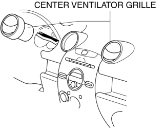
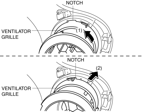
2. Rotate the ventilator grille to the notch in the direction of the arrow (1) shown in the figure and pull it in the direction of the arrow (2) to remove it.
3. Install in the reverse order of removal.
SIDE WALL REMOVAL/INSTALLATION
Right-side
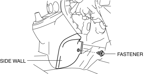
1. Remove the fastener.
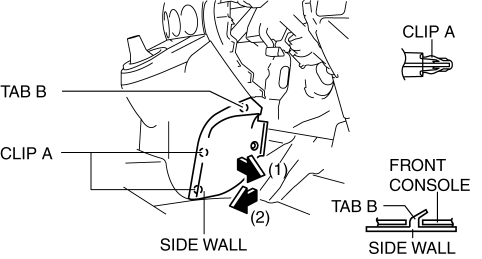
2. Pull the side wall in the direction of the arrow in the order of (1) and (2), then remove it while detaching clips A and tab B.
3. Install in the reverse order of removal.
Left-side
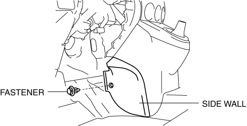
1. Remove the fastener.
2. Pull the side wall in the direction of the arrow in the order of (1) and (2), then remove it while detaching clips A and B and tab C.
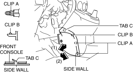
3. Install in the reverse order of removal.
INNER GARNISH REMOVAL/INSTALLATION
1. Disconnect the negative battery cable (vehicles with tweeter).
2. Pull the inner garnish in the direction of the arrow shown in the figure and remove it while detaching the clips.
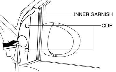
3. Disconnect the tweeter connector (vehicles with tweeter).
4. Install in the reverse order of removal.
SIDE PANEL REMOVAL/INSTALLATION
1. Partially peel back the seaming welt.
2. Remove the following parts:
- Front scuff plate (See FRONT SCUFF PLATE REMOVAL/INSTALLATION).
- Front side trim (See FRONT SIDE TRIM REMOVAL/INSTALLATION).
- Rear console (See REAR CONSOLE REMOVAL/INSTALLATION).
- Shift lever knob (MTX) (See MANUAL TRANSAXLE SHIFT MECHANISM REMOVAL/INSTALLATION).
- Side wall (See SIDE WALL REMOVAL/INSTALLATION).
- Front console component (See FRONT CONSOLE COMPONENT REMOVAL/INSTALLATION).
- Hood release lever (See HOOD LATCH AND RELEASE LEVER REMOVAL/INSTALLATION).
- Lowre panel (See LOWER PANEL REMOVAL/INSTALLATION).
3. Pull the side panel in the direction of the arrow shown in the figure and remove it while detaching clips A and B.
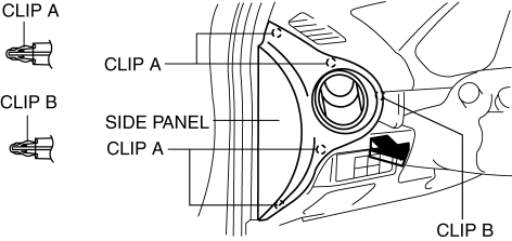
4. Install in the reverse order of removal.
DASHBOARD UNDER COVER REMOVAL/INSTALLATION
1. While pressing the hook inside the service hole in the direction of the arrow (1) shown in the figure, pull the dashboard under cover in the direction of the arrow (2), and then remove the hook and the guide pin.
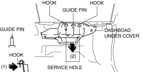
2. Remove the dashboard under cover.
3. Install in the reverse order of removal.

