Mazda 2: Front Console Component
FRONT CONSOLE COMPONENT REMOVAL/INSTALLATION
1. Shift lever to neutral position.
2. Remove the following parts:
- Rear console (See REAR CONSOLE REMOVAL/INSTALLATION).
- Side wall (See SIDE WALL REMOVAL/INSTALLATION).
- Shift lever knob (MTX) (See MANUAL TRANSAXLE SHIFT MECHANISM REMOVAL/INSTALLATION).
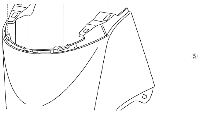
3. Remove the screws, then pull the lower side of the front console component in the direction of the arrow, and remove the clips.
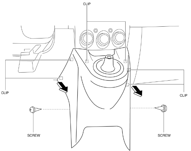
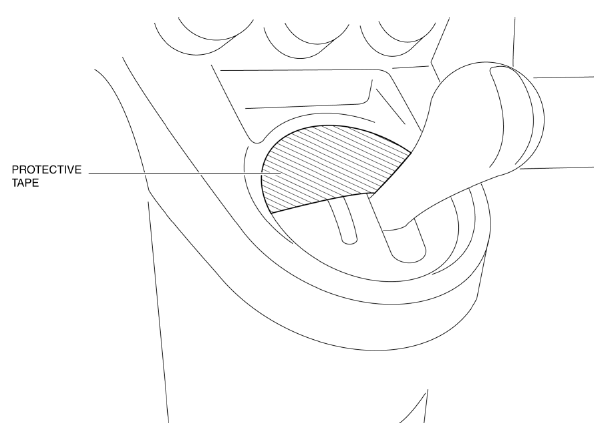
CAUTION:
- Affix protective tape to the AT shift panel to prevent scratches or damage. (ATX)
4. Install the boot panel and front console as a single unit.
5. Install in the reverse order of removal.
FRONT CONSOLE COMPONENT DISASSEMBLY/ASSEMBLY
ATX
1. Disassemble in the order indicated in the table.
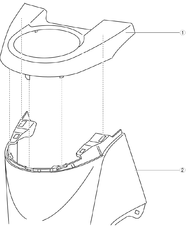
- Boot panel
- Front console
2. Assemble in the reverse order of disassembly.
MTX
1. Disassemble in the order indicated in the table.
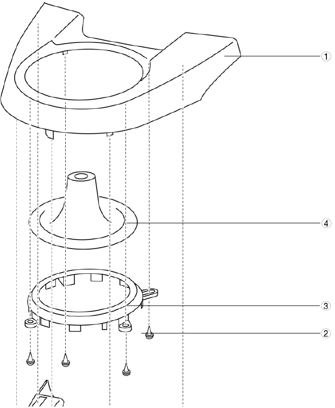
- Boot panel
- Screw
- Set panel
- Boot
- Front console
2. Assemble in the reverse order of disassembly.
REAR CONSOLE REMOVAL/INSTALLATION
1. Disconnect the negative battery cable.
2. Pull the console panel in the direction of the arrow (1), (2) shown in the figure and remove it while detaching hooks A, tab B, and the hooks C.
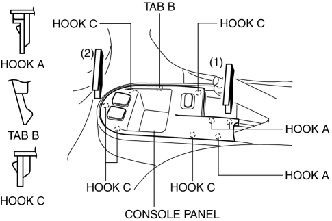
3. Disconnect the auxiliary jack connector and door lock switch connector (vehicles with auxiliary jack).
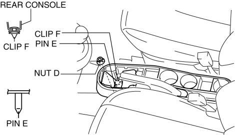
4. Remove nut D, then remove the clip F.
5. Pull up the rear console in the direction of the arrow (3) shown in the figure, remove clips G, move the rear console in the direction of the arrow (4), and remove it avoiding the parking brake lever.
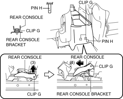
CAUTION:
- When moving the rear console in the direction of the arrow (4), be careful not to damage pins E and H.
6. Install in the reverse order of removal.
A-PILLAR TRIM REMOVAL/INSTALLATION
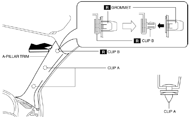
1. Partially peel back the seaming welt.
2. Pull the upper end of the A-pillar trim in the direction of the arrow shown in the figure and remove clips A and B.
3. Cut the lead wire connecting clip B and grommet using a nipper and pull out the A-pillar trim in the direction of the arrow shown in the figure.
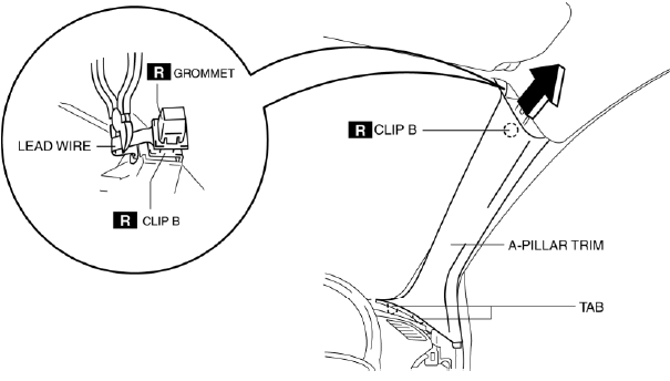
CAUTION:
- When pulling out the A-pillar trim, be careful not to damage the tabs.
4. Move the hook in the direction of arrows (1) and (2) shown in the figure using a flathead screwdriver and detach it from the A-pillar inner panel.
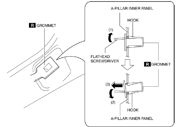
5. Remove the grommet in the direction of the arrow (3) shown in the figure.
6. When installing the A-pillar trim, install the new clip B and grommet to the A-pillar trim in advance.
7. Install in the reverse order of removal.
B-PILLAR UPPER TRIM REMOVAL/INSTALLATION
1. Remove the following parts:
- Adjuster anchor cover (See FRONT SEAT BELT REMOVAL/INSTALLATION).
- Upper anchor installation bolts of the front seat belt (See FRONT SEAT BELT REMOVAL/INSTALLATION).
- Front scuff plate (See FRONT SCUFF PLATE REMOVAL/INSTALLATION).
- Rear scuff plate (See REAR SCUFF PLATE REMOVAL/INSTALLATION).
2. Partially peel back the seaming welt.
3. Remove the B-pillar lower trim. (See B-PILLAR LOWER TRIM REMOVAL/INSTALLATION).
4. Grasp the lower end of the B-pillar upper trim, pull it in the direction of the arrow shown in the figure, and remove hooks A, guide pin B, pins C, and clip D.
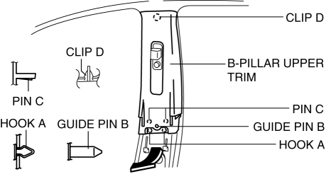
5. Remove the B-pillar upper trim in the direction of the arrow shown in the figure.
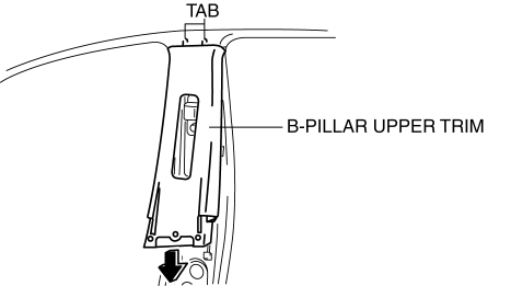
CAUTION:
- When removing the B-pillar upper trim, be careful not to damage the tabs.
6. If there is a remaining clip D, rotate it 90

