Mazda 2: Engine
ENGINE REMOVAL/INSTALLATION
WARNING:
- Fuel vapor is hazardous. It can very easily ignite, causing serious injury and damage. Always keep sparks and flames away from fuel.
- Fuel line spills and leakage are dangerous. Fuel can ignite and cause serious injuries or death and damage. Fuel can also irritate skin and eyes. To prevent this, always complete the "Fuel Line Safety Procedure". (See BEFORE SERVICE PRECAUTION).
NOTE:
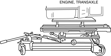
- Perform the engine and transaxle component removal/installation from below the vehicle.
1. Complete the "Fuel Line Safety Procedure", and remove the fuel pump relay. (See BEFORE SERVICE PRECAUTION).
2. Remove the battery and the battery tray. (See BATTERY REMOVAL/INSTALLATION).
3. Drain the engine coolant. (See ENGINE COOLANT REPLACEMENT).
4. Drain the ATF (ATX) or transaxle oil (MTX). (See AUTOMATIC TRANSAXLE FLUID (ATF) REPLACEMENT [FN4A-EL] (ATX) ). (See TRANSAXLE OIL REPLACEMENT [F35M-R] (MTX) ).
5. Remove the front wheels and tires (See GENERAL PROCEDURES (SUSPENSION) ).
6. Disconnect the radiator hose.
7. Remove the fresh-air duct and the air cleaner as a single unit, the evaporative hose, and the air hose. (See INTAKE-AIR SYSTEM REMOVAL/INSTALLATION).
8. Disconnect the fuel hose. (See QUICK RELEASE CONNECTOR REMOVAL/INSTALLATION).
9. Remove the drive belt. (See DRIVE BELT REMOVAL/INSTALLATION).
10. Set the cooler pipe and the cooler hose (LO) out of the way. (See REFRIGERANT LINE REMOVAL/INSTALLATION).
11. Remove the generator. (See GENERATOR REMOVAL/INSTALLATION).
NOTE:
- Secure the A/C compressor using wire or rope so that it is out of the way.
12. Remove the A/C compressor with the pipes still connected. (See A/C COMPRESSOR REMOVAL/INSTALLATION).
13. Disconnect the front drive shafts. (See DRIVE SHAFT REMOVAL/INSTALLATION).
14. Disconnect the selector cable, and wiring harness. (ATX) (See AUTOMATIC TRANSAXLE REMOVAL/INSTALLATION).
15. Disconnect the shift cable. (MTX) (See MANUAL TRANSAXLE REMOVAL/INSTALLATION).
16. Remove the clutch release cylinder with the pipe still connected. (MTX) (See CLUTCH RELEASE CYLINDER REMOVAL/INSTALLATION).
17. Disconnect the vacuum hose and the heater hose.
18. Disconnect the wiring harness from the engine side.
19. Remove the middle pipe or the presilencer. (See EXHAUST SYSTEM REMOVAL/INSTALLATION).
20. Remove in the order indicated in the table.
21. Install in the reverse order of removal.
22. Start the engine. and inspect and adjust the following.
- Leakage of engine oil, engine coolant, ATF (ATX), transaxle oil (MTX), and fuel.
- Pulley and belt for runout and contact.
- Ignition timing and idle speed. Verify the amount of CO, HC. (See ENGINE TUNE-UP).
- Engine-driven accessories operation
NOTE:
- If the engine is overhauled and assembled to the vehicle, perform a road test to verify that there is no abnormal vibration and noise.
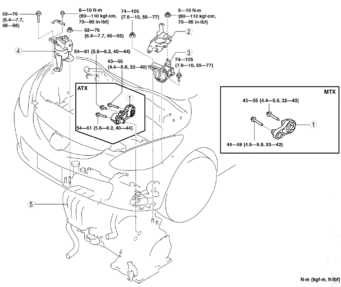
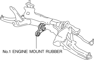
- No.1 Engine mount rubber
- Battery tray bracket
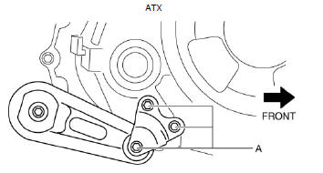
- No.4 Engine mount rubber
- No.3 Engine mount
- Engine, transaxle
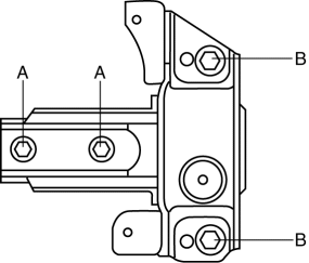
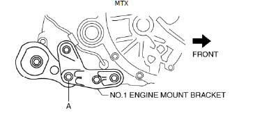
No.1 Engine Mount Removal Note
1. Remove the No.1 engine mount installation bolt (A) from below the vehicle.
2. Remove the No.1 engine mount rubber and the front crossmember as a single unit. (See FRONT CROSSMEMBER REMOVAL/INSTALLATION).
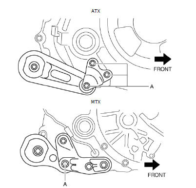
No.3 Engine Mount, No.4 Engine Mount Rubber Removal Note
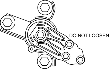
CAUTION:
- Do not loosen the bolt shown in the figure because it cannot be installed properly if loosened once.
1. Secure the engine and the transaxle using an engine jack.

No.3 Engine Mount, No.4 Engine Mount Rubber Installation Note
1. Secure the engine and the transaxle using an engine jack.
2. Install the No.3 engine mount, and then temporarily tighten the installation bolts and nuts.
3. Tighten the installation bolts and nuts by order of A,B.
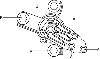
Tightening torque
- 62-76 N*m {6.4-7.7 kgf*m, 46-56 ft*lbf}
4. Install the No.4 engine mount rubber, and then temporarily tighten the installation bolts and nuts.
5. Tighten the installation bolts and nuts by order of A,B.
Tightening torque
- 74-105 N*m {7.6-10 kgf*m, 55-77 ft*lbf}
6. Remove the engine jack and attachment.
No.1 Engine Mount Installation Note
1. Install the front crossmember component. (See FRONT CROSSMEMBER REMOVAL/INSTALLATION).
2. Tighten the No.1 engine mount installation bolt (A).
Tightening torque
- 54-61 N*m {5.6-6.2 kgf*m, 40-44 ft*lbf}
Tightening torque
- 44-58 N*m {4.5-5.9 kgf*m, 33-42 ft*lbf}
Engine Disassembly/Assembly
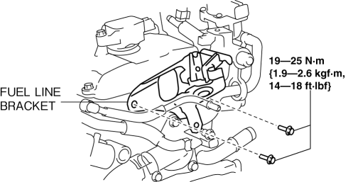
1. Remove the fuel line bracket.
2. Using the bolts part number 99794 1025 or M10

